Yamaha WX7 Repair - Capacitor Replacement
Symptoms
A common fault with the Yamaha WX7 Wind controller is that it will function perfectly well when using the 5 pin MIDI output via the external power pack, whether working on battery or via a mains adaptor, but when connected directly to the WX input on a VL-70m synthesizer it appears to be dead.
Fault and Circuit
Many people make the mistake of thinking it is the VL-70m at fault - after all, you're using exactly the same cable from exactly the same controller, and it works in one socket (via the power pack) but not the other, so that might seem logical. However, the true cause of the fault is that the WX7 requires external power to operate, and the voltage coming out of the WX socket and the voltage coming out of the external power pack, are slightly different. The voltage regulator inside the WX7 can't cope with the difference under fault conditions when there is a problem with the electrolytic capacitors surrounding it.
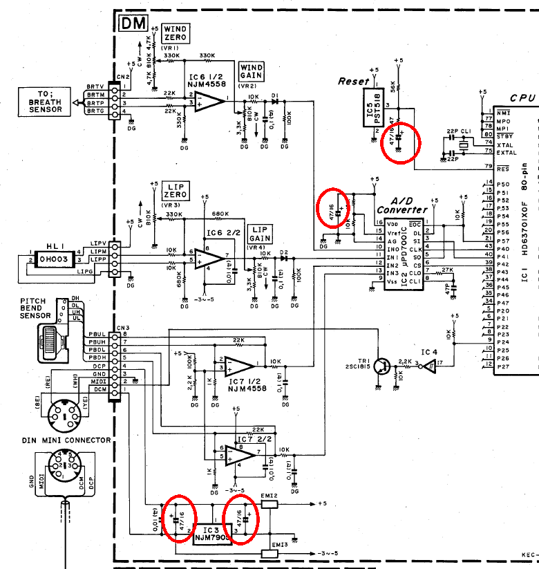
Electrolytic capacitors are notorious for failing after 20 or 30 years. They just get old and the electrolyte dries up. There are four on the circuit board altogether, two on the voltage regulator (bottom of diagram), one on the reset circuit (top), and one on the A/D converter, and it is advisable to replace all four of them.
You Will Need...
- Small posidrive screwdriver
- Soldering iron with the smallest tip that you have, and some considerable skill!
- Solder and solder sucker
- tiny flat blade screwdriver or a craft knife
- 4 Replacement capacitors
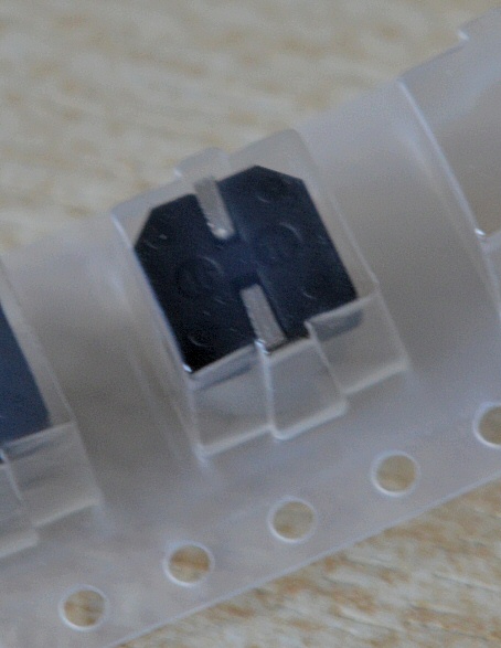
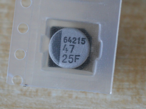
The capacitors we're going to replace are 47uF (microfarad), 16 Volt, surface mount. However, I'd advise replacing them with 25 Volt versions which are the same physical size, the same price, and a higher specification. On eBay in the UK, I paid £2.35 for a pack of 10, with free delivery.
Disassembly
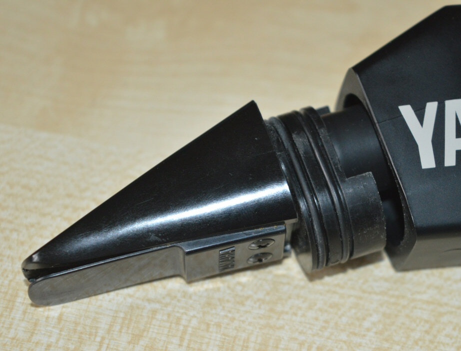
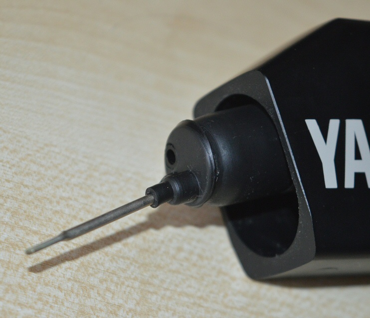
Carefully remove the mouthpiece. It has two tight fitting rubber O-rings on it. It's a tight fit, but mine came off with some gentle wobbling. Be careful not to damage the lip pressor sensor underneath as you remove it |
 |
 |
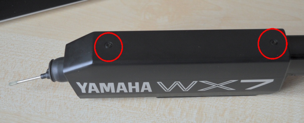
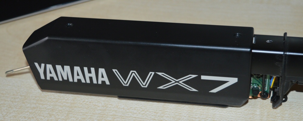
| Remove the two screws from the top of the cover and slide the cover forward over the lip pressor sensor, being careful not to damage it. |
 |
 |
The top left screw must be removed, being careful not to lose the washer underneath.
The top right screw is optional - you don't have to remove this, but the copper screen flaps around if you don't and so it's probably best to remove this screw, and the copper screen with it. |
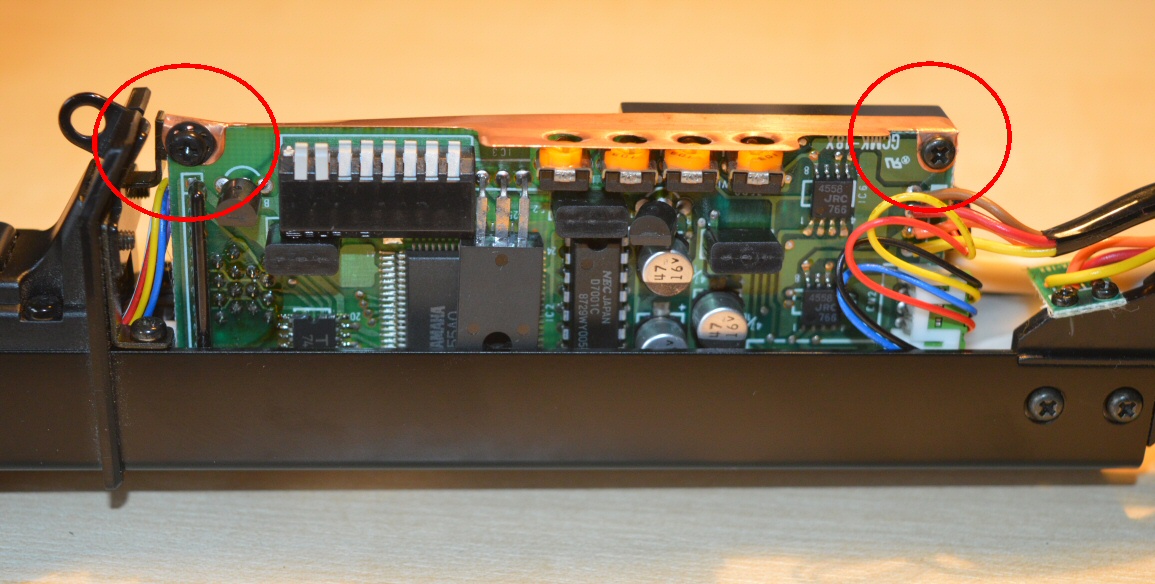 |
| Remove these two screws on the side. You do NOT need to remove the two screws below which hold the breath sensor in place, and I'd recommend that you leave those alone. |
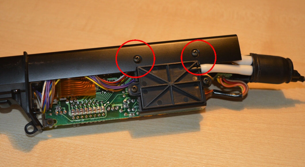 |
| It is not necessary to remove any more screws or to unplug any cables. With a bit of care you can reposition the circuit board so that you can get access to the four silver capacitors. You don't need access to the underside of the circuit board, everything is done from the top. |
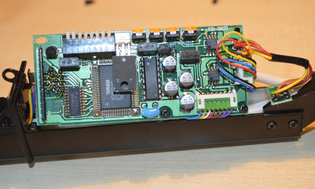 |
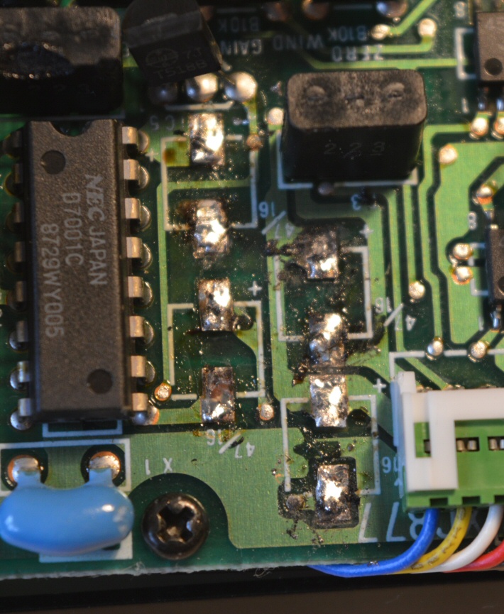
The four old capacitors need removing. I found it easiest to start from the bottom one up. You will see from the photo of the underside of the new capacitors above that the two legs of the capacitor do not extend beyond the body of the capacitor. You can also see from the photo of the circuit board above that each capacitor has a solder pad top and bottom to which it is attached, and that pad DOES extend beyond the body of the capacitor. When you heat the solder on the solder pad, the heat (and the solder) flow underneath the capacitor to attach it. The best method I found to remove the capacitor was to heat the pad for a second or two and to remove as much excess solder as possible using a solder sucker. I then placed a sharp flat bladed screwdriver (or you could use a craft knife) under the capacitor and to carefully lever up one side of the capacitor at the same time as applying the soldering iron to the pad once again. Then repeat with the other side of the capacitor,
but this time you can use gravity to assist with the capacitor falling off the board and you don't need to suck the solder off.
To attach the new capacitors, I started at the top and worked downwards. I first applied some solder to all of the pads in preparation. Then, with each capacitor, place it over the solder pads, noting the correct orientation - the black line on the capacitor body must face the correct direction. Apply some light pressure down onto the circuit board then melt the solder on the pads, one at a time. This will cause the solder to flow under the capacitor and attach it. Repeat with the other three capacitors.
Assembly is the reverse of disassembly. Position the circuit board back correctly. Attach the two side screws, then the two which hold the copper screen, being sure to get the one with the washer in the correct hole. Slide the cover back over the mouthpiece, being careful with the lip sensor - I found that the sensor catches slightly on the cover, but with care it is ok. Finally, put the two case screws back in, and you're done. |
 |
|